【研究背景】
由于其高的理论比容量(4200 mAh g-1)和适宜的工作电位,硅基负极取代传统石墨负极能使锂离子电池能量密度大大提升。太阳能光伏废硅产量大,以此为原料制备高性能电池负极材料,可以实现高性能锂离子电池的同时,解决光伏固体废弃物污染问题。阻碍硅基负极实际应用的最大问题之一是硅基材料锂化/脱锂过程中活性材料与液体电解质之间持续的副反应以及在循环过程中固体电解质界面(SEI)的不断增厚,并伴随着液体电解质与活性锂的不断消耗,导致阻抗不断增加,电化学性能迅速衰退。因此,稳定的电极/电解质界面结构对改善硅基负极的电化学性能至关重要。
【文章简介】
近日,华中科技大学武汉光电国家研究中心孙永明教授课题组联合清华大学王莉教授在“中国科学”系列SCIENCE CHINA Chemistry上发表题为“In situ formation of ionically conductive nanointerphase on Si particles for stable battery anode”的研究工作。
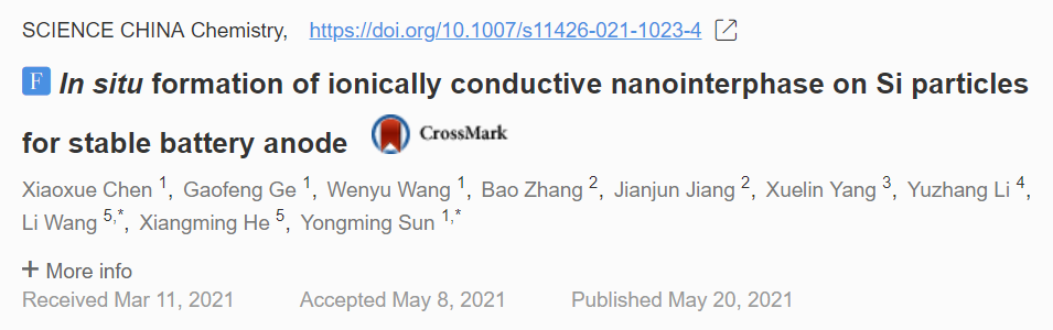
本研究通过红磷(red P)与太阳能光伏废硅(Si)之间的简单机械合金反应,在硅颗粒表面构建化学键合的硅磷核壳结构(Si-P)。在首次锂化过程中,P纳米壳层转化为同形磷化锂(Li3P)层并在后续的循环中保持其结构稳定。Li3P纳米壳层减少活性硅与电解液的直接接触,从而抑制了持续副反应;同时,该壳层提供了高的离子电导率,提高了硅基负极的倍率性能和循环性能。
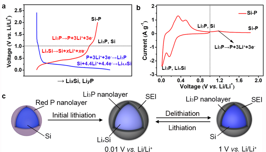
Figure 1. Electrochemical cycling of Si–P core-shell composite. (a) The first-cycle voltage-lithiation degree plot and (b) cyclic voltammograms (CVs) of Si–P electrode at 0.1 mV s−1. (c) Schematic of a Si−P core-shell structured particle during the lithiation/delithiation cycling in the cutoff potential range of 0.01–1 V (vs. Li/Li+). During the initial lithiation process, P irreversibly converts to Li3P and Li in Li3P will not be extracted below 1 V (vs. Li/Li+). A stable Si(LixSiy)–Li3P core-shell structure is formed during the following electrochemical cycling in the cutoff potential range of 0.01–1 V (vs. Li/Li+)
【本文要点】
要点一:通过红磷(P)和太阳能光伏废硅(Si)之间简单的机械合金反应,在硅颗粒表面构建化学键合的硅磷核壳结构(Si-P)。在首次锂化过程中,P纳米壳层转化为同形磷化锂(Li3P)层并在后续的循环中保持其结构稳定。高离子电导Li3P纳米层的稳定存在改善了硅基负极的电化学性能。
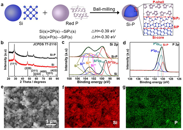
Figure 2. Fabrication and characterizations of Si–P core-shell structures. (a) Schematic of the fabrication of Si–P core-shell structures by using a ball-milling approach using Si and red P as the starting materials. During the ball-milling process, a mechanical alloying reaction takes place to form Si–P bonding. (b) XRD patterns for the pristine Si (bottom) and Si–P composite (top). (c) High-resolution Si 2p XPS spectra for the pristine Si (bottom) and Si–P composite (top). (d) High-resolution P 2p XPS spectrum for the Si–P composite. SEM image of (e) the Si–P composite and corresponding EDS mapping images of Si (f) and P (g).
要点二: Li3P纳米壳层有效减少活性硅与电解液的直接接触,抑制了界面处持续的副反应,实现电极/电解质界面结构的稳定;同时大大提高了界面处的离子电导,提高硅基负极的倍率性能和循环性能。
Figure 3. TEM images of the Si–P composite. (a) High-resolution TEM image of the Si–P composite. (b) Dark-field TEM image and (d–f) the corresponding EDS mapping images of Si and P for the Si–P composite. (c) EDS count-position plot across a particle in (b).
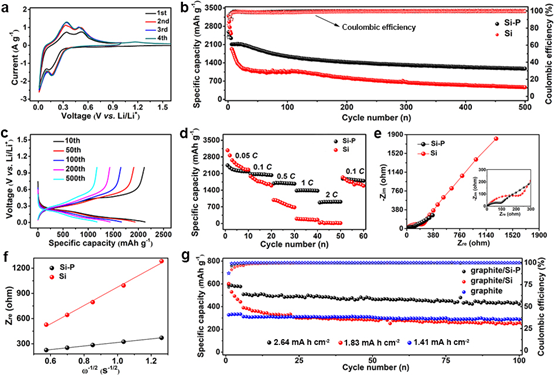
Figure 4. Electrochemical performances of the Si–P composite. (a) CV curves of the Si–P electrode at 0.1 mV s−1. (b) Electrochemical cycling performances of the Si–P (black) and pristine Si (red) electrodes, and (c) the corresponding voltage-capacity profiles of the Si–P electrode. The initial five charge/discharge cycles were performed at a current density of 200 mA g−1, and the subsequent cycles were conducted at a current density of 1,200 mA g−1. (d) The electrochemical cycling of the pristine Si (red) and Si–P (black) electrodes at various C rates (C rate was calculated based on 4,200 mA g−1). (e) Nyquist plots of the Si (red) and Si–P (black) electrodes after 50 charge/discharge cycles in the frequency range of 100 mHz–1,000 kHz. (f) Low-frequency relationships between Zre and ω−1/2 of Si (red) and Si–P (black) electrodes after 50 charge/discharge cycles. (g) Capacity-cycle plots of graphite/Si–P, graphite/Si, and bare graphite electrodes with similar active mass loading (4.5–5.2 mg cm−2) cycled at 100 mA g−1 after 5 activation cycles at 50 mA g−1.
要点三:在商业石墨材料中加入15% Si-P复合材料后,石墨/Si-P混合电极在电流密度为100 mA g-1下展现高的面容量为2.64 mAh cm-2和高的可逆比容量为447 mAh g-1,循环100次后容量保持率达88.3%,展现了其作为实际锂离子电池负极的应用前景。
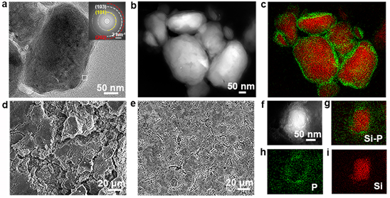
Figure 5. Characterizations of Si–P and pristine Si after cycling. (a) TEM image of the Si–P composite after 1st charge/discharge cycle. (b) Dark-field TEM image and (c) the elemental mapping images of the Si–P composite after 1 discharge/charge cycle. SEM images of (d) the Si electrode and (e) the Si–P electrode after 50 charge/discharge cycles. (f) Dark-field TEM image and (g–i) elemental mapping images of the Si–P composite after 50 charge/discharge cycles.
以下为专访部分
导师专访
导师解析:((该领域目前存在的问题?这篇文章的重点、亮点。)
硅基电极材料活性物质与电解液的持续副反应及界面结构不稳定性严重影响了其电化学性能,阻碍了其实际产业应用。本研究通过机械合金反应在硅颗粒表面构筑磷纳米层;并利用其与硅工作电位差,使该磷纳米层在电极工作过程中原位转化为稳定的Li3P纳米界面层,减少活性物质与电解液的直接接触,并提高界面离子导电性,提高了硅基材料的电化学稳定性。
导师点评:(您对该领域的今后研究的指导意见和展望)
硅基材料具有极高的理论比容量和适宜的工作电位,是最有潜力的下一代高比能锂离子电池负极材料。硅基负极材料的界面结构及其在电化学循环过程中的演化对其电化学循环和倍率性能产生至关重要的影响。推动高性能硅基材料大大规模应用,将来的研究应聚焦提高其界面结构的稳定性、界面离子导电性等问题。
导师照片:

第一作者专访:
1.该研究的设计思路和灵感来源
界面结构的不稳定性是阻碍硅基负极材料实际应用的最大问题之一。构建稳定的离子导电的界面结构能有效提高硅基材料的电化学性能。
2.该实验难点有哪些?(如:材料合成,材料表征与测试)
实验的难点应该是工作量大和周期长。一方面,我们需要不断优化材料配比以获得最佳的性能;另一方面,硅基负极材料的电化学性能评测周期长。
3.该报道与其它类似报道最大的区别在哪里?(如:机理,表征,性能等)
本研究利用硅磷化学成键能力,采用简单的机械合金方法在硅颗粒表面构建硅磷核壳结构(Si-P)。利用硅基材料与磷的工作电压差异,P纳米壳层转化为同形磷化锂(Li3P)层,并在电化学循环中保持稳定。界面处引入含Li3P纳米层,在减少界面副反应的同时,提高了界面的离子电导。从工艺的角度,利用简单机械球磨工艺稳定界面结构,具有操作简单、经济的特点。
原文链接|孙永明、王莉教授Sci. China Chem. :原位形成离子导电纳米界面实现稳定高比能硅负极